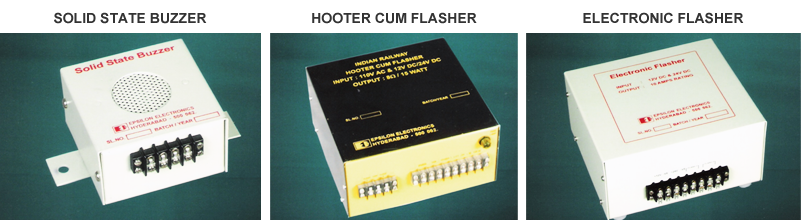
TRACK FEED BATTERY CHARGER
|
SPECIFICATION NO : IRS:S:89/93 (AMENDMENT NO.2) |
STATUS : PART-I |
|
|
The Track Feed Battery Charger is used to charge 1 or 2 or 3 or 4 lead acid cells of 40 / 80 AH used in DC Track Circuits. 5 AMP. FOR CHARGING 40 AH BATTERY 10 AMP. FOR CHARGING 80 AH BATTERY It has a Double-Pole ON/OFF Rotary Switch, 110V AC Input Terminals and another Terminal for Earth are provided. DC Output Terminals are provided in the Front Panel. A Potential free contact is available to extend audiovisual alarm at remote place. A snap acting rotary (1 Pole / 4 Way) cell selector switch is provided for selecting 1, 2, 3 or 4 cells in four positions. |
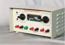  |
DUAL BANK BATTERY CHARGER
|
SPECIFICATION NO : IRS:S:85/92 (AMENDMENT NO.3) |
STATUS : PART-II |
|
|
The Dual Bank Battery Charger is a Reliable Battery Charging Equipment and is of interlocked type with internal isolation available between the charging and discharging banks. It shall charge one set of batteries, while the other set of batteries is connected with the load for operating the block circuit. Subsequently, the designed set of batteries shall be put on charge by connecting it to the charger, while the charged set of batteries shall be connected to the load through a switch provided on the charger. The charger is designed for continuous operation at rated voltage and current at ambient temperature 0-55º C. The unit has over load and short circuit protection. The entire system is housed in an MS Box of 1 mm thickness and has electrostatic epoxy powder coating. The Charger is housed in an MS Box of 1 mm thickness, with slots for ventilation and is covered with a wire mesh. |
 |
FAIL SAFE ELECTRONIC TIME DELAY DEVICE
|
SPECIFICATION NO : IRS:S:61/2000 (AMENDMENT NO.1) |
STATUS : PART-I |
|||||||||||||||||||||||||||||||||
|
The device is used to Control Railway Signalling Circuits where a set time delay is required. The device works on 24V OR 60V DC (+20% & -10%). The Electronic Fail Safe Device is designed to provide fixed time delay based on counting of pulses. The device provides time delays of 60 OR 120 Seconds (-0% to +10%). The construction of the device is robust. The device is housed in a Q Type Base and cover. The whole assembly is capable of being mounted on a relay rack and is protected against dust and moisture. Gasketing by suitable material conforming to IS:11149 is provided. Any other Time Delay Setting can be provided on Specification.
DELAY TIMER TYPE 1010 SERIES The Time Delay Unit Type 1010A is assembled in an ABS Plastic Moulded Box with 35mm DIN Rail Mounting. 3 LED Monitors are provided on the top. A 10 position Dip Switch is provided for time setting from 1 to 10 Seconds. This unit is suitable for continuous working in Railway Installations for indoor use.
CONNECTIONS : To the Terminals as shown in figure. TIME SETTINGS : To set the delay time, open screws on the anodized label on the top and select one time setting out of the 10 settings as per requirement. |
 |
|||||||||||||||||||||||||||||||||
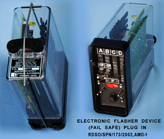
FAIL SAFE FLASHER UNIT
|
SPECIFICATION NO : RDSO/SPN/173/2002 (Amendment No.1) |
STATUS : PART-I |
|
|
The Fail Safe Electronic Flasher Device manufactured by EPSILON is suitable for giving direct flashing supply to be used on Interlocking Panel(s) and / or driving a 24V DC neutral relay. The Flasher Device works on 24V DC and gives 24V DC nominal output. The design of the Circuit is of Fail Safe nature to ensure that no steady output is delivered in case of failure or open circuit / short circuit or ageing of any component or any momentary switching OFF / ON of the Power Supply or external surges. The Flasher Device is provided with protection against reverse polarity of supply. Any supply wrongly connected across its output shall not damage the device. The Flasher device is mounted on ‘Q’ Series Relay housing and is protected against dust and moisture. This Product can be provided WITH OR WITHOUT GALVANIC ISOLATION. |
 |
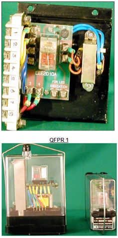
ELECTRIC LAMP FILAMENT SWITCHING UNIT FOR COLOUR LIGHT SIGNAL
|
SPECIFICATION NO : IRS:S:100/2002 |
STATUS : PART-I |
|
|
The Filament Switching Unit is suitable for both 12V, 24W and 12V, 33W Triple Pole Lamps. It is possible to fix the Electronic Lamp Filament Switching Unit in both Colour Light Signals Unit as well as in location box provided near the Signal Post. ‘H’ Type Transformer is used in the Filament Switching Unit. This can also be supplied in Q-Type Relay Base (QFPR I) WEIGHT : 0.800 Kg. (Approx.) |
 |
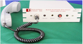
BLOCK TELEPHONE WITH DYNAMIC INSETS
|
The BLOCK TELEPHONE has Two Parts : |
STATUS : PART-I |
|||||||||||||||
|
The Handset is made of ABS Plastic and has a Metallic Hook Clamp. It has Electro Dynamic Transmitter and Receiver Insets. It has a PTT Switch and 6 Way Coiled Cord Terminated with ‘U’ Clips to be connected to the Induction Coil / Amplifier Unit.
WEIGHT : 2.650 Kg. (Approx.) |
 |
|||||||||||||||
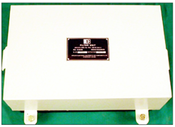
DTMF BASED ELECTRONIC BLOCK BELL AND BLOCK TELEPHONE EQUIPMENT
|
SPECIFICATION NO : RDSO/SPN/191/2005 |
STATUS : PART-II |
|
|
DTMF Based Electronic Block Bell and Block Telephone Equipment is meant to be used in the place of Conventional Block Bell Equipment and Block Telephones. This Equipment is used for calling by DTMF Signalling and Communication via 2 Wire Line through OFC or Quad Cable to the other end station where the tone is decoded and an audio-visual indication is activated. Similarly the tone from the other end station also is received by the first end station. The Signalling and Speech Circuit arrangement works on 24V DC + 20% - 30%. Any Equipment can be used for ‘UP’ or ‘DOWN’ Signalling by using a DIP Switch provided inside the Equipment assembled in an aluminium box, duly powder coated. The Charger is housed in an MS Box of 1 mm thickness, with slots for ventilation and is covered with a wire mesh. |
 |
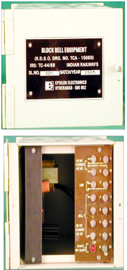
BLOCK BELL EQUIPMENT
|
SPECIFICATION NO : IRS:TC:44/88 (Amendment No.1) |
STATUS : PART-I |
|
|
The Block Bell Equipment is a part of the block instrument which is provided at the end of the block sections at cabins / ASMs. DC impulses cannot be sent in AC electrified area since block circuit is converted from overhead alignment to underground cable terminated as terminating transformer at both of the ends. This Equipment is used in AC electrified area to convert the DC impulses to AC at the sending end and AC impulses to DC all the receiving end. The Equipment is a single transistor oscillator to give 45V AC across 1120 ohms. This also has a full wave rectifier circuit to rectify the received AC Voltage and to energize a relay. The plunger is connected to Terminals TS9 and TS10 of terminal strip (Refer Circuit diagram enclosed). When the plunger is pressed 12 VDC supply is fed simultaneously to the Transistor Oscillator and the Relay So/2. The output of the oscillator, Viz, 45 Volts at 150 Hz, is thus made available at terminals. TS3 and TS11 through the energized contacts of Relay So/2. This is fed to the line. At the distant station, this voltage from the line is fed to terminals TS3 and TS11 at the Block Bell Equipment installed at the station. Though the normally closed contacts of Relay So/2, this voltage is fed to the bridge rectifier. This rectified voltage is available, as desired from terminal TS4 and any of the other terminals, namely, TS5, TS6, TS7, TS12, TS13, TS14 and TS15 for ringing the bell. When the plunger is operated, the single transistor is energized of the Oscillator gives an output 60V (open circuit) @ 150 Hz and 45V (across 1120 ohms) at 50 Hz, sinusoidal at TS3 and TS11. WEIGHT : 2 ½ Kg. (Approx.) |
 |
BLOCK FILTER UNIT
|
SPECIFICATION NO : IRS:S:68/89 |
STATUS : PART-I |
|
|
The Block Filter Units are arranged in Single Line and Double Line Block Circuits for the protection of instruments as well as staff from the influence of inducted voltage in 25KV AC Electrified Section. This unit consists of 4 Nos. of Chokes, 2 Nos. of 4 Terminals of condensers, 2 Nos. of Lightening Discharges wired as shown in the sketch. The Chokes L1, L2, L3 and L4 are wound on stalloy cores and fixed in a metallic box and filled with insulating compound and sealed. 4 Terminal condensers (Sealed Type) are used to block DC path. The Equipment uses 2 Nos. of Gas Discharge Tubes for further protection. The mechanical construction of the Equipment is rugged and the unit can be wall mounted as per Drawing No. RDSO/TC/33075. It is of tropical finish and capable of working satisfactorily under conditions of Temperature, Humidity and Dust normally encountered in service conditions. All exposed parts are plated, painted or otherwise protected against corrosion. The Equipment is supplied with a M.S Bracket and Rag Bolts for Wall Mounting. WEIGHT : 50 Kgs. (Approx.) |
 |
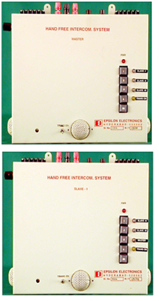
HAND FREE TALK BACK SYSTEM (1 MASTER + 3 SLAVES)
|
The Hand Free Inter Communication System consists of One Master + 3 Slaves and is used for Hand Free Inter Communication between Master to Slave and Slave to Slave, using Dual Tone Multiple Frequency (DTMF) Calling. It is a Duplex System using Two Tones in Voice Frequency Band for Selective Calling a particular Slave or Master. Caller Identification is provided visually with the aid of a Dual LED which is provided in each unit. When a call is received the Caller’s designated LED will glow Green in the Master and when the Trans become ‘ON’, the Green LED changes to RED. Each Equipment consists of the following :
Depending on Consignee’s requirement, 1 Master + 4 Slaves can be supplied |
 |
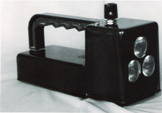
LED BASED BATTERY OPERATED TORCH LIGHT CUM FLASHER HAND SIGNAL LAMP
|
SPECIFICATION NO : RDSO/SPN/195/2008 |
||
|
EPSILON has developed Battery Operated LED Based Torch Light Cum Flashing Hand Signal Lamp for the Indian Railways. The above Torch Light is made with the latest state of the art design to have long battery life with maximum efficiency. SALIENT FEATURES :
APPLICATION AREAS :
WEIGHT : 16.0 Kg. (Approx.) |
 |