

ELECTRONIC LC GATE TELEPHONE SYSTEM
SPECIFICATION NO : RDSO/SPN/TC-51/2011 REV.2.0 |
STATUS : PART-I |
|
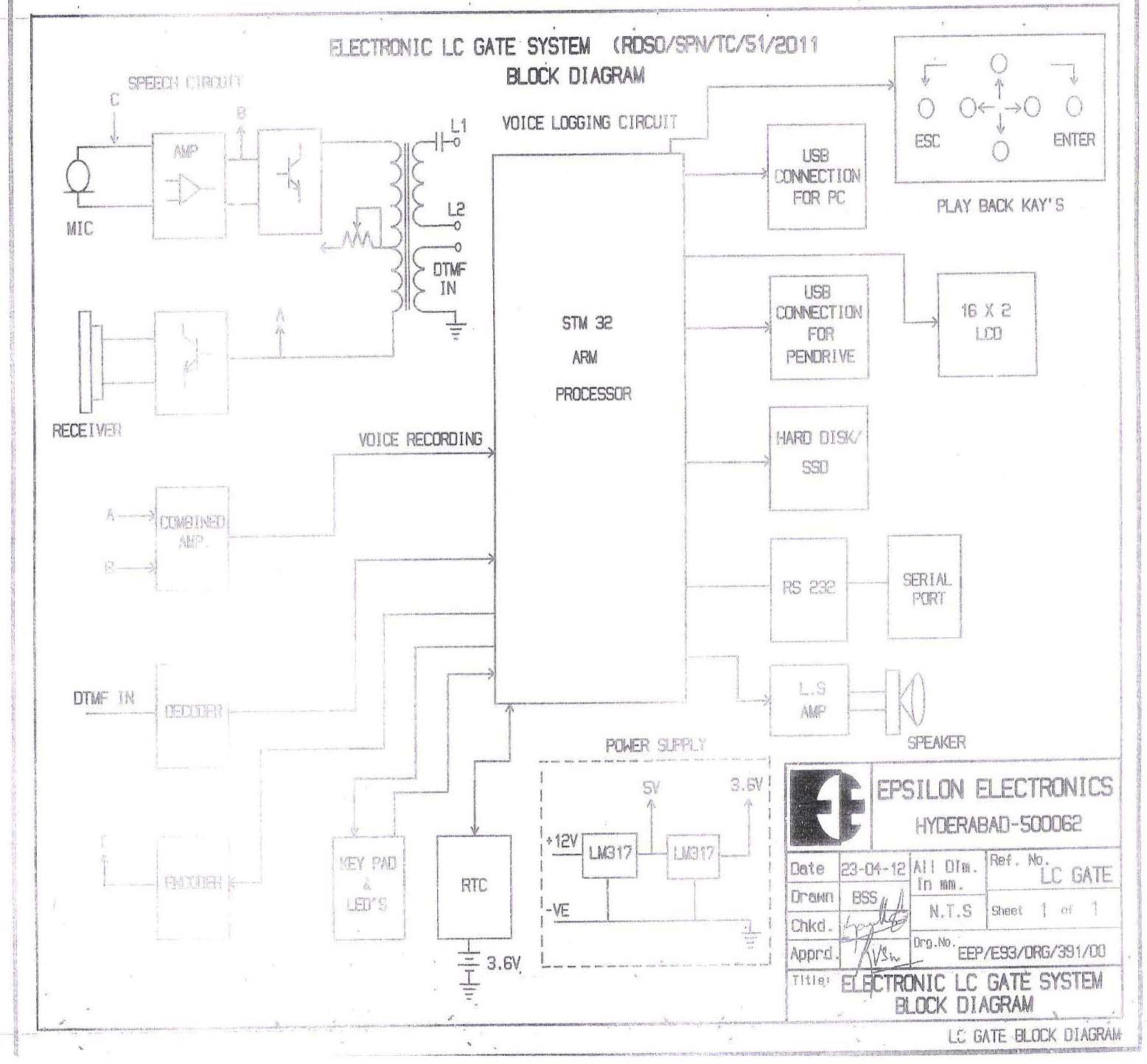
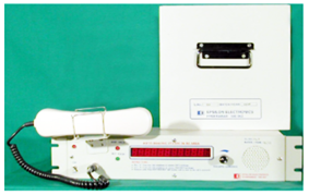
Centrallised Power Supply, eliminates power supplies at Gates thus enables Easy Maintenance. Privacy of conversation Cost Effective The Master Telephone Unit as per Rev.2 has Voice Logging Facility working on 24V/12V DC supply or 48VDC available from OFC Hut. • Time, Date, Year • Station ID • Calling / Called number in the ASM Cabin. • Called / Received Time and Duration. • Recording of events chronologically. Shall have provision to store minimum 200 hours of conversation on 8GB SSD. Built-in Speaker for listening recording of calls or live call monitoring. Automatic recording of all events occurring in the Master Telephone. Facility to replay last call by pressing one key. USB Cable Socket and interfacing to PC. Wave file auto copying facility. Application Software Installation CD provided. User interface key pad for assigning Station ID, correction of date / time etc. Well engineered dust free Master Unit. Current Consumption : Idle : 150 mA, During Speech : 250 mA, Ringing / Recording : 350 mA maximum.
|
 |
|
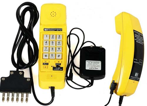
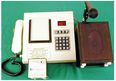
WAY SIDE TELEPHONE FOR AUTO DIALLING SYSTEM
SPECIFICATION NO : IRS:TC-83/2007 |
STATUS : PART-I |
|
As per the Specification Clause No: 3.0 The Way Side Telephone consists of
Assembled in a Wooden Box and this weights over 7.5 Kgms. As per the field user’s report it is too heavy to carry and they expressed that this should be of light weight. WEIGHT :900 Gms. (Approx.) |
 |
|
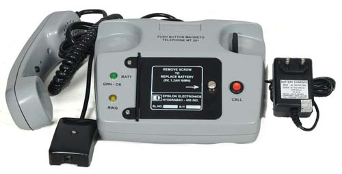
PUSH BUTTON MAGNETO TELEPHONE (MTI 201)
SPECIFICATION NO : IRS:TC-83/2007 |
STATUS : PART-I |
|
This Push Button Magneto Telephone is similar to the Rotating Type Magneto Telephone, but the Ring Generator is Electronic and appears across the Lines as along as the ‘Press To Call’ (PTC) button is pressed. SCOPE : |
 |
|
New Electronic LC Gate Telephone System – Station Telephone
SPECIFICATION NO : RDSO/SPN/TC-51/2011 REV.2.0 |
STATUS : PART-I |
||||||||||||||
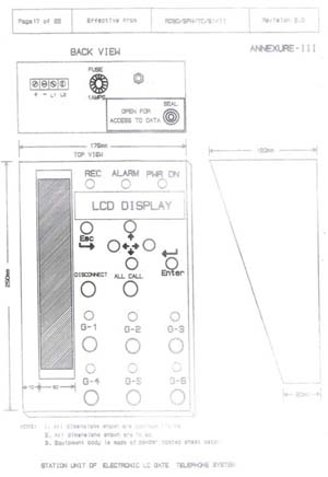
1. LCD & Keypad Description The LCD used here is an alphanumeric character display with two lines of 16 characters each. • The Keypad consists of 6 keys and two LEDs. Out of six keys, four are direction keys – UP, DOWN, LEFT and RIGHT. The other two keys are ENTER and ESCAPE. • The LEFT and RIGHT keys are used to select the position of cursor. These are enabled for time, date and station ID setting operations. • The UP and DOWN keys are used to scroll through the menu items and also to edit the alphanumeric characters in time, date and station ID setting operations. • The ENTER key is used to select an operation displayed on Line 2 of the LCD. • The ESCAPE key is used to come out of the menu or discard any operation in progress. One LED is used to acknowledge the key press on the keypad. It blinks momentarily once a key is detected.
2. Idle State The LCD when ‘idle’ displays Date and Time on the Line1 and Station Id on Line 2. An example display is given below. Note: Station Id is a 16-character string consisting of 16 alphanumeric characters without any spaces in between. The same string is used in audio record file naming. When display is ‘idle’ state, it displays the call progress messages on Line2 and returns to ‘Station Id’ display when there are no calls in progress. Sample displays are shown below.
The other strings that are displayed for other call states are: "Calling ALL... " 3. Main Menu The following are five main menu items available for user. "'Play Voice File"
• When display is idle, press “ENTER” key to enter into main menu display on Line2. Note: Press “ESC” key to come out of main menu and to set display idle.
When Line2 of the display is showing “’Play Voice File” press ENTER key to enter into playback menu. User will be given the following two options based on the state of the operation.
NOTE: Please make sure that speaker is switched ON for playback. When at least one call is recorded from the time the unit is powered ON (or reset), the option to play latest record also will be given to the user. Else, it allows only selecting stored records. When display is showing “Play latest rec?”, pressing the ENTER key triggers the playback of the latest recorded voice file. The display will be as shown below during playback.
NOTE: Pressing ESC key will terminate the playback of voice record. When “Play stored rec?” option is selected, it starts from displaying the first record/file name from the stored voice records. The filename is displayed without station Id as shown below. When ENTER key is pressed, the displayed file is selected for playback and the display will be as shown below
NOTE: If there are no voice records available, the same will be informed to the operator as “No files found!”. format: <Station Id>_YYYYMMDD_HHMMSS_<In/Out>_G<a/1/2/3/4/5/6> Once the playback of selected file is done, it will display the “Done!” as shown below.
Then operator is allowed to select next file from the list of files available in the unit. NOTE: Pressing ESC key will terminate the playing back of voice record. If there are no more files to display, the display shows “End of records!!”. 5. Setting Station ID
Press ENTER key when Line2 of the display as above, to set/edit the station identification. It shows the current station id of the unit and allows user to edit each position/character of the Line2.
The cursor is shown as blinking character (or as a block for space). The cursor position can be selected using LEFT or RIGHT keys. The character at cursor position can be changed by pressing UP or DOWN keys. Only alphanumeric characters and “space” are allowed in the following sequence. 6. Setting Time
Press ENTER key when Line2 of the display as above, to set/edit the unit time. It displays the current time of the internal real time clock (RTC) of the unit. Then, the user is allowed to edit the time as shown below.
NOTE: Time is always in 24-Hour format. Use LEFT and RIGHT keys to select the digit to edit. The cursor is shown as blinking character. Use UP and DOWN keys to select a number from 0 to 9. Once the required time is entered, press ENTER to set the internal RTC time with this value. The same will be displayed on the display during Idle State of the display. 7. Setting Date
Press ENTER key when Line2 of the display as above, to set/edit the unit date. It displays the current date of the internal real time clock (RTC) of the unit. Then, the user is allowed to edit the date as shown below.
8. Copying Voice Records to USB Pen Drive
Press ENTER key when Line2 of the display as above, to initiate copy of internal voice records to a USB memory device. First it tries to detect the USB device, if plugged in the USB-A receptacle connector provided at the rear side of the station telephone unit. During this process the display shows the status as below.
There may be no device available or not a memory device with FAT file system. If a valid device is detected, it starts copying internal WAV files one by one to the device. The display shows these states as shown below.
During successful copying of files, it shows the file numbers that are being copied to USB device. Once copying of all files is done it gives confirmation and asks to remove the USB device from the connector as shown below. If copying is interrupted by an incoming/outgoing call, the same will be informed to the user as shown below.
NOTE: Please make sure that USB Pen drive is formatted with FAT file system and sufficient free memory is available for the copy of voice records. |
 |
||||||||||||||


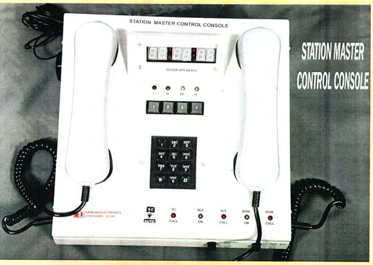
STATION MASTER CONTROL CONSOLE
SPECIFICATION NO :IRS:TC-60/2007 |
STATUS : PART-I |
|
GENERAL A. 4 WIRE MODE (IRS:TC-60/2007) B. 2 WIRE MODE (IRS:TC-80/2000) OR (IRS:TC-79/2000) C. AUTO MODE OPERATION : AUTO MODE : |
 |
|
V.F. Tapping / Termination Transformers
SPECIFICATION NO : IRS:TC:22/1976 |
STATUS : PART-I |
|
The Voice Frequency and V.F Signalling Transformers manufactured by Epsilon are used for derivation and termination of Underground Telecommunication Cable Circuits. The Side Circuits of the paper insulated V.F Quads, which are loaded are used for the transmission of Speech of the unloaded phantom for derivation and termination of Underground Telecommunication Cable Circuits. The side circuits are used for transmission of interrupted 50 Hz rising current for Signaling. The Transformers are manufactured in four types as follows :-
Other Impedance Ratio are also available on request, such as 470 : 470, 470 : 600, 600 : 600. |
||
VF TRANSFORMER BAY
RDSO DRAWING NO : TCA - 15201 (ADV) |
STATUS : PART-I |
|
The V.F Transformer Bay manufactured by EPSILON is used in the communication line of Railway Electrification area to ensure systematic installation of V.F Transformers for use in various circuits. The V.F Transformer Bay houses up to 54 Transformers. All the Types of Transformers, namely V.F Tapping, Terminating and Signalling Transformers are housed in this Bay as per the requirements in the Circuit. Krone Type Connectors are provided for Wiring Incoming / Outgoing Cables. Link Panels are used for establishing Isolation / Connection on the lines in the Section. Integrated Line Protection Circuits are provided for each Quad. The Bay is constructed out of M.S. Steel Sheets complete with 5 Rows of Link Panels, Aluminum Sections for mounting the transformer and copper earthing strip. It is of sturdy construction and ensures compactness. The doors are made with reinforcement to avoid tilt. Grommets are provided for cable entries. Copper Strip is provided for earthing. Link Panels are as per ITI Specifications DE 224008/A. Links as per ITI Spec. No. BL/57279 are also supplied along with the Bay. Brackets are also provided for cable harnessing. |
TRANSFORMER ASSEMBLY FOR THERMO-SHRINKABLE JOINTS (2T/3T)
RDSO DRAWING NO : IRS:TC-76/2000stem |
STATUS : PART-I |
|
The 2T / 3T Transformer Joints are used for Termination and Derivation of the Circuits for PET Unloaded PIJF 4 Quad Cables. Two Transformers are assembled inside a brass tube with flying leads taken out through the marked holes in the covers. The assembly is filled up with epoxy compound and then hermetically sealed. This joint is meant to be used with thermo shrinkable sleeves. The Transformers are manufactured in Five Types as per the Impedance Ratio required :
Each Type has been designed to have a very good insulation between the windings and also between the windings and the case. They can easily withstand a voltage of 2KV (r.m.s) 50 Hz between the windings and the case. |
||
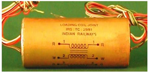
LOADING COIL ASSEMBLY FOR THERMO - SHRINKABLE JOINTS
CONFORMING TO : IRS:TC:29/81 (88 mH OR 118 mH) |
STATUS : PART-I |
|
The Loading Coil Joint manufactured by EPSILON consists of four numbers of Loading Coils of 88 mH OR 118 mH assembled inside a brass tube for loading of 4 Quad Cables. The coils are potted with epoxy compound and lid is sealed after taking the leads for wiring. This joint is meant for use with thermo shrinkable sleeves. |
 |
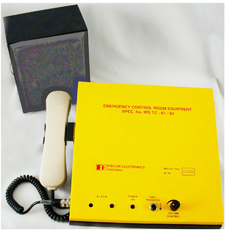
EMERGENCY PORTABLE CONTROL TELEPHONES (2 WIRE AND 4 WIRE)
SPECIFICATION NO : IRS:TC:75/99 (Amendment No.2) |
STATUS : PART-I |
|
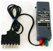
The Portable Emergency Control Telephone manufactured by EPSILON is a part of the 4 Wire / 2 Wire Emergency Train Traffic Control System. This Telephone provides inter communication between any Way Side point along the train route and the Controller. This can be connected through 6 Pin Socket located along the Railway Track in 4 Wire Side and 2 Wire Side. The Telephone has ‘Trans’ and ‘Receive’ Speech Circuits. The Telephone works on 3V DC with the aid of 2 Nos. of 1.5V dry cells. The entire Circuit, HMT and the Battery container are housed inside the M.S. Body provided with shoulder strap for ease of use. With the aid of a Switch, this Telephone can be selected for 2 Wire or 4 Wire operation. It is provided with a 6 Pin Plug. EMERGENCY PORTABLE CONTROL TELEPHONES (2 WIRE AND 4 WIRE) 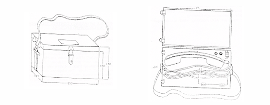 |
 |
LIGHT WEIGHT PORTABLE CONTROL TELEPHONES (2 WIRE AND 4 WIRE)
SPECIFICATION NO : IRS:TC:78/2000 (Amendment No.1) |
STATUS : PART-I |
|
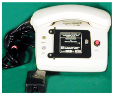
The Light Weight Portable Control Telephone, which was first enclosed in ABS Plastic Moulded Box by EPSILON, is a part of the 4 Wire / 2 Wire Emergency Train Traffic Control System. The Telephone provides inter communication between any Way Side point along the train route and the Controller with 4 Wire / 2 Wire PECT. This Telephone can be connected through 6 Pin Socket located along the Railway Track in 4 Wire Side or 2 Wire Side. The Telephone has ‘Trans’ and ‘Receive’ dry cells. With the aid of a Switch, the Battery is connected to the Circuit and with the aid of another Switch, this Telephone can be selected for 2 Wire or 4 Wire operation. |
 |
AUTO DIALING SYSTEM - BASE UNIT AND WAY SIDE TELEPHONE
SPECIFICATION NO : IRS:TC:83/2007(Amendment No.1) |
STATUS : PART-II |
|
The System is capable of connecting RAILWAY Exchange and DOT Exchange by pressing the designated button from the Way Side Telephone through the Base Unit in the Test Room. Way Side Telephone will work similar to Auto Telephone and becomes either Subscriber of RAILWAY Exchange by pressing * or DOT Exchange by pressing # connection is achieved automatically. The Auto Dialing System consists of a Base Unit with CPU (Central Processing Unit) and interface unit consisting of 4 Wire / 2 Wire conversion and amplification circuitry, for networking between RAILWAY Telephone Exchange, DOT Telephone Exchange and RAILWAY OMNIBUS / Way Side Equipment in RE area. The “BASE UNIT” is installed in the Test Room which can monitor the conversation. This System consists of 2 Parts :
WEIGHT : 14.0 Kgs. (Approx.) |
 |
EMERGENCY 6 PIN PLUG / SOCKET AND BOX
SPECIFICATION NO : IRS:TC:42/87 (Amendment Slip No.1) |
STATUS : PART-I |
|
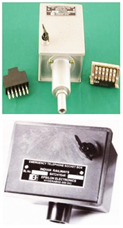
EPSILON manufactures Six Pin Plug and Socket used for 4 Wire Communication on Emergency Control Circuits from the points provided for this purpose along the side of the Track in AC electrified areas. These are made of Polycarbonate Plastic (unbreakable). Socket shall be fixed in the Socket Box which is also manufactured by EPSILON. The Socket shall be wired to the Trans Receive of the Emergency Control Circuit, derived from the main cable through Transformer Joint. The Socket Box is of 2 Types :
WEIGHT : Socket Box Mild Steel - 1 ½ Kgs. (Approx.) & ABS Plastic - 0.200 Kgms (Approx.) |
 |
DESK TYPE ELECTRONIC MAGNETO TELEPHONES
SPECIFICATION NO : IRS:TC:79/2000 (Amendment No.2) |
STATUS : PART-I |
|
Electronic Magneto Telephone manufactured by EPSILON is an extended version of Magneto Telephone having additional feature of One Push Button Calling in place of Hand Generator. It is possible to interface this Telephone with Microwave and Optical Fibre System. It can be used for point to point communication between Cabin ASMs of a yard, Cabin to Level Crossing Gates and between Two Level Crossing Gates etc. The Circuit works on 3V DC source 2 Nos. Dry Battery Type R - 20 to IS : 8144 to be used. A Battery compartment is provided on the front of the Telephone, with a hinged cover and screw. WEIGHT : < 1.0 Kg. (Approx.) |
 |
DESK TYPE 2 WIRE / 12 WAY DTMF SELECTIVE CALLING TELEPHONES
SPECIFICATION NO : IRS:TC:80/2000 (Amendment No.1) |
STATUS : PART-I |
|
EPSILON Make Selective Calling Equipment is used for operation on overhead cable, microwave or fibre optic link. This is electronic extended version of Magneto Telephone having additional features of 4 x 3 Push Button Matrix for Calling 11 Station in 12 Way DTMF Telephone. It can also be used as an intercom between the parties. Any one can be designated as Master and others as Slave. The Selective Calling Equipment is designed with advanced digital circuitry techniques. This System will generate DTMF Code for Signalling the distant station as per CCITT Standards. It is possible to assign a maximum of 10 Station Codes. Ring back tone is available to the Calling Station on the reception of assigned Code and communication with called station is established through the handset provided. Every Telephone shall be assigned a distinct calling code. It shall be possible to send the Signalling code even when two or more parties are in conversation. WEIGHT : < 1 Kg. (Approx.) |
|
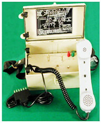
ELECTRONIC LEVEL CROSSING GATE TELEPHONE
SPECIFICATION NO : RDSO/SPN/TC/51/2009 (Rev.1.0) |
STATUS : PART-II |
|
The Electronic Level Crossing Gate Telephone features include :
WEIGHT : 2.5 Kgs. (Approx.) 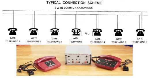 |
||
2 WIRE / 4 WIRE CONTROL OFFICE EQUIPMENT
SPECIFICATION NO : IRS:TC:60/2007 |
STATUS : PART-I |
|
The Control Office Equipment manufactured by EPSILON is used for Train Traffic Control with Voice Frequency Signalling, using Dual Tone Multiple Frequency (DTMF) Signals as per CCITT recommendations for 4 Wire and 2 Wire Operations. It is meant for use in Omnibus Speech Circuits like Section Traction Power and Deputy Controls used in Railways using 4 Wire Transmission Circuits employing 2 Tones in Voice Frequency Band for Selectively Calling of the Station / Party concerned. The Controller can select any of the 99 Stations. The System works on 2 Wire mode by connecting a 4 Wire to 2 Wire Conversion Unit to the 4 Wire Control Office Equipment. This Equipment consists of :
WEIGHT : 10.0 Kg. (Approx.) |
 |
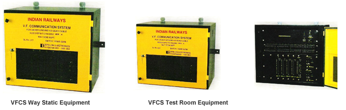
VOICE FREQUENCY COMMUNICATION SYSTEM FOR UNDERGROUND QUAD CABLE
SPECIFICATION NO : RDSO/SPN/TC/34/2002 (Ver.4) |
STATUS : PART-II |
|
The Voice Frequency Communication System is used with Underground PET 4/6 Quad Cable of 0.9mm dia, having characteristic impedance of 470 ohms vide Specification No. IRS:TC:30/07 for Telecommunication between Way Side Stations and Control Office / Test Room. By using this System, the PET Quad need not be loaded to compensate the uneven attenuation characteristics over the voice band. There shall be no need for balancing. The typical characteristics of the cable is that the attenuation (losses) increases with frequency in the band of 300 - 3400 Hz. The Equalizer Amplifier designed for the System has the counter characteristics to equalize the cable losses in the V.F. Band of 300 to 3400 Hz. The System comprises of :
WEIGHT : 40.0 Kgs. (Approx.) |
||
RDSO/SPN/TC/34/2002 (Ver.4) |
STATUS : PART-I |
|
 |
||
4 WIRE TO 2 WIRE SPEECH CONVERSION UNIT
STATUS : PART-I |
||
ACTIVE The “ACTIVE” 4 Wire to 2 Wire Speech Conversion Unit is designed to suit the 4 Wire Control Room Equipment. The design is such that the side tone is kept as minimum as possible for 2 Wire impedance of 600 ohms, and does not need lead adjustment, etc. Trans and Receive gain adjustments are possible with the aid of preset potentiometers. The Equipment operates on 12V DC. PASSIVE The “PASSIVE” version of the 4 Wire to 2 Wire Speech Conversion Unit is designed to achieve a leak better than -25dB to 2 Wire impedance of 600 ohms. This may be used along with the Control Room Equipment as per IRS:TC:60/2007 to convert the 4 Wire Control Room Equipment to 2 Wire Control Room Equipment. |
 |
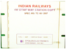
DTMF TYPE 4 WIRE WAY STATION EQUIPMENT
SPECIFICATION NO : IRS:TC:60/2007 (DECODER) |
STATUS : PART-I |
|
The Control Way Station Equipment consists of a wall mounted cabinet containing Signal Reception, Recognition, Ringing and Ring Back Transmission Circuit called collectively Decoder and the Voice Communication Equipment. It is housed in a rigid box, avoiding any opening for dust etc. The front has a hinged door which, after opening gives access P.C. Board wired with Decoder Circuit and Trans / Receive Amplifiers. The Hand Micro Telephone is as per IRS-TC-38/97 with an LED Lamp to indicate that the Station is called and a Buzzer for hooting while the Station is called. The front has a hinged door which, after opening gives access P.C. Board wired with Decoder Circuit and Trans / Receive Amplifiers. The Hand Micro Telephone is as per IRS-TC-38/97 with an LED Lamp to indicate that the Station is called and a Buzzer for hooting while the Station is called. It is possible to assign any DTMF Code - 1 to 99 and / or A, B, C, D by setting the DIP Switches I and II (10 Position) and III (4 Position) for A, B, C or D. The PCB is clearly marked for identification 0 to 9, A, B, C and D etc. On receipt of the selected code, it shall decode and electronic buzzer shall hoot and a Red LED provided on the HMT is lighted. The LED shall continue to be lit till the handset is lifted from the cradle Double cutting relay contacts for both Trans and Receive Amplifiers are provided apart from the Isolation Transformers, to isolate the line from the equipment. Ring Back Tone of the required level shall appear in the Trans Terminals. ‘MOVR’ Based Surge Protection is employed across the RX Lines. This Decoder operates on 12V DC. WEIGHT : 2.650 Kg. (Approx.) |
 |
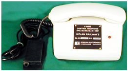
4 WIRE CONTROL TELEPHONE
SPECIFICATION NO : IRS:TC:38/97 (Amendment No.1) |
STATUS : PART-I |
|
The 4 Wire Way Station Control Telephone manufactured by EPSILON is to be used with 4 Wire Way Station Equipment, which is installed on the Way Side Stations. The 4 Wire Way Station Control Telephone consists of Dynamic Type Transmitter and Receiver Insets (RT 200). It has an Audio / Visual indication at the called Station. The Body, Handset and other plastic parts are of ABS Plastic. It consists of 1.5 Meter long Coiled Cord and a Straight Cord terminated in a Rosette Box. This Telephone works on 12V. WEIGHT : 0.590 Kg. (Approx.) |
 |
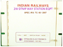
DTMF TYPE 2 WIRE WAY STATION EQUIPMENT
SPECIFICATION NO : IRS:TC:60/2007 (DECODER) |
STATUS : PART-I |
|
The Control Way Station Equipment comprises of a wall mounted cabinet containing Signal Reception, Recognition, Ringing and Ring Back Transmission Circuit called collectively as the Decoder and Two Wire Control Telephone. It is possible to assign any DTMF Code to the Way Station Equipment, 1 to 99 and / or A, B, C and D by setting the DIP Switches I and II (10 Position) and III (4 Position) for Group Codes (A, B, C, D). This ensures a firm and rigid connection. The code selection terminals are clearly marked in the Decoder PCB. On receipt of the pre-selected code, it shall decode and it shall give Audio / Visual Indication in the 2 Wire Control Telephone. The Equipment is housed in a Metal Box similar to that of the 4 Wire Way Side Station Decoder. This Decoder operates on 12V DC. WEIGHT : 2.650 Kg. (Approx.) |
 |
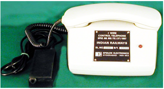
2 WIRE CONTROL TELEPHONE
SPECIFICATION NO : IRS:TC:37/97 (Amendment No.1) |
STATUS : PART-I |
|
The 2 Wire Way Station Control Telephone manufactured by EPSILON is to be used with 2 Wire Way Station Equipment, which is installed on the Way Side Stations. The 2 Wire Way Station Control Telephone consists of Dynamic Type Transmitter and Receiver Insets. It has a LED Lamp to indicate that the Station is Called and a Buzzer for hooting while the Station is Called. It has a Pre-Amplifier Circuit give output voltage of 775 mV across the line with 600 ohms load impedance at the input of 5 mV across the Dynamic Type Transmitter. The 2 Wire Control Telephone consists of ABS Body, Hand Micro Telephone, with Press to Talk Micro Switch, Cradle Switch, Coil Cord and Straight Cord, 6 Way Rosette Box, Buzzer and LED. The Body, Handset and other plastic parts are of ABS Plastic. It consists of 1.5 Meter long Coiled Cord and a Straight Cord terminated in a Rosette Box. This Telephone works on 12V. WEIGHT : 1 Kg. (Approx.) |
 |
EMERGENCY CONTROL ROOM EQUIPMENT
SPECIFICATION NO : CONFORMING TO IRS:TC:61/93 |
||
This Equipment is also an associated unit with the Test Room Equipment. The Control Room Equipment (IRS:TC:60/2007) can be supplied duly modified to do the functions of the Emergency Control Room Equipment. All Controls are provided in the Table Top Equipment and the Loud Speaker Unit is kept separately. WEIGHT : 15.0 Kg. (Approx.) |
 |
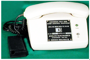
UNIVERSAL DTMF TYPE WAY SIDE STATION TELEPHONE (2 WIRE / 4 WIRE)
SPECIFICATION NO : IRS:TC:82/2005 (Amendment No.1) |
STATUS : PART-I |
|
This Equipment is used for Control Communication on 4 Wire / 2 Wire Circuits. The Telephone includes circuitry of conventional Control Telephone as well as Way Station Equipment Decoder. The Telephone is assembled in Siemens Type ABS Plastic Body and is capable of work on both 4 Wire and 2 Wire Omnibus Circuits by using a changeover switch provided inside the Telephone and works on :
The Telephone will work on 12V DC with ± 20% supply voltage. |
 |
2 WIREPRIMARY LINE PROTECTION BOX
This protection box manufactured by EPSILON shall be used in series with the 2 Wire Line for Surge Protection. This consists of protective devices having the required ratings of Voltage and Current. It has Gas Discharge Tubes / MOVR and current sensing Poly Switches. The Circuit is assembled in a PCB and has 3 input leads and 3 output leads for L1, L2 and Ground. This is housed in a M.S. Box duly paint protected, with Name Place, Cable Entry Holes, Grommet etc. WEIGHT : 0.200 Kg. (Approx.) |
 |
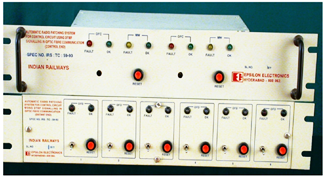
AUTOMATIC RADIO PATCHING UNIT
SPECIFICATION NO : IRS:TC:59/93 |
|
|
Automatic Radio Patching System for Control / Far Ends using DTMF Signalling for OFC System with Dedicated / Without Dedicated Channels. Control End Relay kept in Control Office Works on 12V DC and the Distance End Relay kept in the OFC Building works on 48V DC. This unit is optionally available for Control End / Far End with or without 4 Way Branching Network. WEIGHT : 12.0 Kg. (Approx.) |
 |
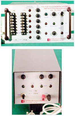
POWER SUPPLY UNIT FOR WAY SIDE STATION EQUIPMENT
SPECIFICATION NO : IRS:TC:72/97 (Amendment No.1) |
STATUS : PART-I |
|
This SMPS Based Power Supply Unit can support a maximum of six numbers of Way Station Equipment using DTMF Signalling as per Specification IRS:TC:60/2007. The Power Supply Unit is designed with advanced circuitry techniques with required line and load regulation and very low output ripple, as well as Electrical Protection against Over Voltage, Over Load, Short Circuit and Reverse Polarity of the Battery Connection of Power Supply Unit (both when Power Supply Unit is ON and OFF). It is supplied with Maintenance Free Value Regulated (Sealed) Lead Acid Batteries (12V/7AH) that conform to Specification IRS:S:93/96. The Power Supply Unit can provide either One Output (1 Amp.) OR Six Outputs (0.2 Amps. each) for Six Way Station Equipment through 6 Pairs of Terminals. WEIGHT : 9.0 Kg. (Approx.) |
 |
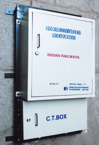
CABLE TERMINATION BOX
The Cable Termination Box can be supplied for 5 - 20 Pairs as per the requirement. The Box is rugged, weatherproof, and highly reliable and uses Universal Test Disconnect Terminal Blocks of PHOENIX OR WAGO Make. WEIGHT : 2.0 Kg. (Approx.) 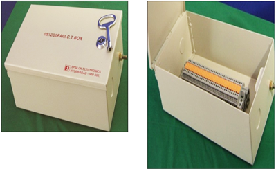 |
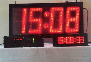
DIGITAL CLOCK WITH GPS SYNCHRONIZED DIGITAL CLOCK
SPECIFICATION NO. RDSO/SPN/TC/62/2008 (Rev-3.0) |
STATUS : PART-II |
|||||||||||||||||||||||||||||||||||||||||||||||||||||||||||||||||||||||||||||||||
The Digital Clocks use Global Positioning System (GPS) to Synchronize accurate time and are networked (wired and wireless) systems consisting of One Master Clock and several Clocks for Platform and Office. Master Clock receives time from GPS receiver and sends the same periodically to synchronize all Slave Clocks connected to it. The synchronized time is sent through wired (RS-485) or wireless. SALIENT FEATURES :
APPLICATION AREAS :
Technical Specifications : |
 |
|||||||||||||||||||||||||||||||||||||||||||||||||||||||||||||||||||||||||||||||||
|
||||||||||||||||||||||||||||||||||||||||||||||||||||||||||||||||||||||||||||||||||
Control Communication Equipment for OFC, using 2 Wire Telephones (CCEO)-(Under Development)
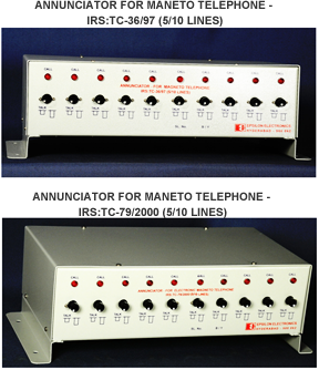
ANNUNCIATOR FOR MULTIWAY TELEPHONE EXCHANGE CONFORMING TO RDSO DRG. NO. TCA:3352 (ADV)
EPSILON Make Annunciator is engineered with Electronic Circuitry is designed with SCRs, Ringer and Ringer ICs, having Audio Visuals (LED and Buzzer) indications. The Desk Type Annunciator is Assembled in a Metal Box duly Powder Coated. The mechanical arrangement is improved version of RDSO Drg. No. TCA : 3352 (Adv). EPSILON has Two Models :
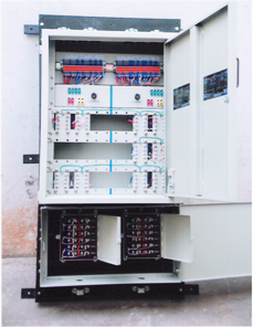
The Units are available for 5 or 10 Lines. In both the Models, the LED of the Unit shall glow till the Master Switches ‘ON’ the TALK Switch of the Called Slave. The Buzzer shall hoot as long as the Caller Rings. One number of the respective Magneto Telephone (as per IRS:TC-36/97 or IRS:TC-79/2000) shall be provided by the Purchaser as the Master, which shall be connected to the Annunciator Unit. (*) NOTE : THE MAGNETO TELEPHONE TO BE CONNECTED TO THE ANNUNCIATOR DOES NOT FORM PART OF OUR SUPPLY. 6 QUAD CABLE ARRANGEMENTS 6 Quad Cable Arrangements in RE area along with OFC at Station shall be made for providing communication facilities between Stations. For providing the above communication facilities equipment has to be manufactured and installed as per the Drawing No. B/SG/P/Drg/Tele/1/2008 supplied by the Railways and shall be provided with the following equipment :
II Internal wiring of the equipment shall be done using 02 Pair Switch Board Cable as per Drg. No. B/SG/P/Misc/50/2008.
The wiring shall be made as per the drawing supplied by the Railways as under : Quad 1 - Block : This Quad shall be connected to the Block Circuit through 470 : 1120 VF Transformer (IRS:TC:22/76). 470 Ohms impedance is to be connected to cable side and 1120 Ohms impedance is to be connected to the Block Instrument side. Quad 2 - IBS : This Quad shall be connected to the Axle Counter Working. Quad 3 - EC :
Quad 4/1 - LC Gate : 1 : 2 Signal Transformer as per IRS:TC:22/76 shall be provided, as the distance between Station and L.C Gate is more than 7.5 Kms. For DTMF Selective Calling Phones, Circuit without 1 : 2 Signal Transformer is to be provided. Quad 4/2 - TAWS : TAWS Circuit shall be connected in this pair. Quad 5 - BPAC : BPAC Circuit shall be provided in this pair. Quad 6/1 - Auto Phone : This Circuit shall be provided through 2 Pole / 3 Way Rotary Switch for selecting the Railway Exchange or DOT or OFC. Quad 6/2 - IB Phone : This Circuit shall be connected through 1 : 2 Signal Transformer as per IRS:TC:22/76 for Magneto Telephone. Provision for Talk Back System without Transformer shall be made in this pair. |
 |
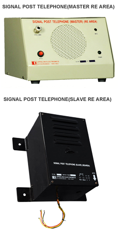
SIGNAL POST TELEPHONE (SPT) - SIMPLEX
I. RE AREA The Signal Post Telephone (SPT) consists of :
SCOPE : This is similar to the above, but due to heavy induction in the cable due to 25KV AC overhead lines, it has separate Power Supply with the Slave (24VDC) and it has specially designed filter to remove the induced voltage in the cable. MASTER TELEPHONE (MT) : This is kept on the Desk of the ASM to facilitate communication between ASM (MT) and the loco driver (ST) for controlling movement of train. This consists of a Microphone Amplifier, Loud Speaker and a Press To Talk Switch. The Master (MT) and the Slave (ST) have separate power supplies of 24VDC each. Provision is given on the front panel to adjust the output level by using a Potentiometer.
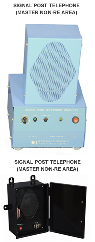
Only 2 Wires shall be wired between Master Telephone and Slave Telephone. SLAVE TELEPHONE (ST) : The Slave Telephone is kept on the Signal Post (IBS) at a convenient height. This consists of the Microphone, Amplifier, Loud Speaker and a Press To Talk Switch. A Potentiometer is provided inside the unit to adjust the output level. The conversation would be in the ‘Half Duplex’ mode and the Slave Telephone has to be connected to the 24VDC Power Supply Unit. As an option we can provide operation from 110VAC, 50 Hz also at extra cost. II. NON RE AREA The Signal Post Telephone (SPT) consists of :
The System is Simplex (Only one can talk at a time) MASTER TELEPHONE (MT) : This is kept on the desk of ASM to facilitate communication between Assistant Station Master (Master Telephone) and the Slave Telephone for the Loco Driver in connection with movement of trains. This consists of a Voice Amplifier, Loud Speaker, Audio Visual Indications (Buzzer and LED) Power ‘ON’ LED, ‘Call Transfer’ Switch and a ‘Press to Talk’ Switch (PTT). The System works on 12V DC power Source. Only 2 Wires shall be wired between Master Telephone and Slave Telephone. The Master Telephone is housed in a Metal Box duly powder coated and facilitates hand free listening. When the call is received from Slave Telephone, the Buzzer hoots and a RED Led glows. The Master Switches ‘ON’ the ‘Call Transfer’ Switch and the Master Telephone shall be able to listen Slave Telephone’s Speech in the Loud Speaker. When the Master Telephone wants to talk to the Slave Telephone, he has to press the ‘Press to Talk’ Switch. After the conversation is over, the ‘Call Transfer’ Switch is switched to normal position.
SLAVE TELEPHONE (ST) This is kept on a Signal Post (IBS) fixed rigidly at a convenient height. The enclosure is Weather Proof, Rugged and Powder Coated. This consists of a Loud Speaker and a ‘Press to Call’ Switch. By pressing this Switch the Master Telephone gets an Audio Visual Indication and the Master Telephone presses the ‘Call Transfer’ Switch and the communication between Master Telephone and Slave Telephone is established. Whenever the Switch is pressed by the Driver; he gets a Ring Back Tone to indicate that the Assistant Station Master has received the Call Signal. After the conversation, the Driver does not have to Switch Off anything. No Power Supply required. |
  |